A common modelling requirement is a pair of connected zones where fresh air is supplied to one zone only and extracted from the other, with air transferring between them through a door undercut or a transfer grille. Typical examples are a living room supplied and a bathroom extracted, or a restaurant supplied and a kitchen extracted.
This article describes the options available in DesignBuilder for representing this arrangement, together with the limitations of each.
- Choosing an option:
The appropriate option depends on two questions: whether the extracted air is returned to the air handling unit, so that heat recovery on the extract has to be represented, and whether the extract zone requires its own heating or cooling.
Extract zone not conditioned | Extract zone conditioned | |
Extracted air returned to the air handling unit (heat recovery represented) | Option 1 - Return plenum | Option 3 - Transfer air balanced through the return air nodes (scripting) |
Extracted air discharged to outside (no heat recovery) | Option 2 - Zone exhaust fan with a transfer air path | Option 2 - Zone exhaust fan with a transfer air path |
- Why this arrangement needs particular attention:
In EnergyPlus the return air flow rate of a zone is derived from its supply air flow rate. A zone with no supply air therefore has no return air path, and reducing the supply flow to zero does not on its own turn a zone into an extract zone.
Interzone airflow is also one-way. A flow defined from a source zone to a receiving zone enters the energy and mass balance of the receiving zone only, and the source zone is unaffected. The air is not removed from the source zone, and the transferred air has no connection to the air loop, so it does not reach a heat recovery device.
- Defining the transfer air path:
Options 2 and 3 both start from a transfer air path between the two zones, defined as Interzone Airflow. Interzone airflow uses the EnergyPlus ZoneMixing object, which applies to any transfer between zones and is not restricted to natural ventilation. The dialog is reached from the Tools menu only when the Scheduled natural ventilation model option is set, which is where the impression that it is a natural ventilation feature usually comes from.
1. Set the Natural ventilation model option to Scheduled.
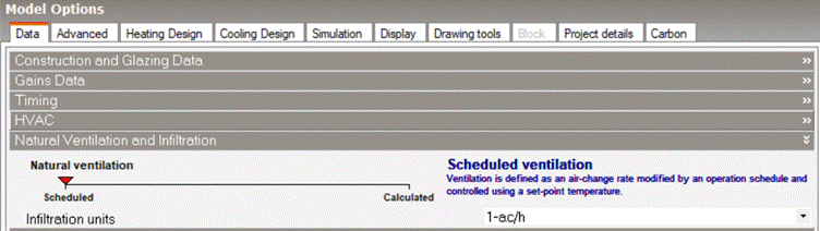
2. Open Tools > Interzone Airflow and select Add.
3. Set the source zone, the destination zone and the design volume flow rate. Check the flow rate units selected on the main dialog before entering the value.
4. Set the schedule. Where the transfer is driven by a mechanical system, use the air system availability schedule rather than a continuous schedule, so that the transfer stops when the fans stop.
5. Set Delta temperature to 0, so that the transfer occurs regardless of the relative zone temperatures. A positive value requires the source zone to be that much warmer than the receiving zone before any transfer occurs, which will switch the transfer off permanently where the receiving zone is the warmer of the two.

Note that, used on its own, a transfer air path represents only the thermal effect of the transferred air on the receiving zone. The receiving zone gains the air with no corresponding outlet, and the air loop return is unchanged. This is appropriate only where the receiving zone response is the sole interest. To represent a complete ventilation arrangement, combine it with Option 2 or Option 3.
- Option 1 - Return plenum:
Use this option where the extract zone does not require its own HVAC system and the extracted air is returned to the air handling unit. It is the only option within the interface that places the extract zone directly in the air loop return path, so the extracted air reaches the heat recovery device at the extract zone condition. No transfer air path is required.
1. Place the supplied zone in the HVAC zone group and set its air distribution unit to the design supply flow rate.
2. Assign the extract zone to a return plenum component, replacing the return mixer on the air loop demand side.
3. Enable heat recovery on the air handling unit outdoor air system, and set the outdoor air flow rate equal to the supply flow rate so that all return air is relieved through the heat exchanger rather than recirculated.
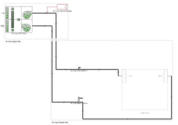
Supply and return plenums are solved in the heat balance as thermal zones and exchange heat with adjacent zones through their surfaces, so the extract zone air temperature is calculated as normal and the return air arrives at the heat exchanger at that temperature.
Note that plenums are uncontrolled zones and cannot incorporate HVAC equipment. Where the extract zone has to hold a temperature setpoint from a radiator or other equipment, it cannot also be a plenum.
- Option 2 - Zone exhaust fan with a transfer air path:
Use this option where the extracted air is discharged to outside without heat recovery, for example a kitchen extract hood, a bathroom extract fan or a mechanical extract ventilation system. The extract zone can be conditioned or not.
1. Define the transfer air path from the supplied zone to the extract zone, as described above.
2. Add a zone exhaust fan to the extract zone, with a flow rate equal to the transfer air flow rate.
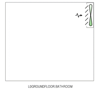
The zone exhaust fan extracts zone air to outside. It is a standalone component that does not link in with the air loop, and it can be added to a zone group without any other HVAC equipment where no other system is required. It does not by itself drive any mixing, ventilation or infiltration flow, which is why the transfer air path is needed to represent the make-up air.
Note that air extracted in this way leaves direct to outside and does not pass through the air handling unit heat exchanger, so heat recovery on the extract is not represented. Note also that the source zone continues to return its full supply flow to the air loop, because the transfer air path does not remove air from it.
Where Calculated natural ventilation is used, a zone with an exhaust fan also requires one corresponding vent from the Zone Exhaust Fans category, placed on an external surface.
- Option 3 - Transfer air balanced through the return air nodes:
NOTE: This option requires the scripting module activated in DesignBuilder.
This is the only option in which the extracted air reaches the air handling unit at the extract zone condition while the extract zone remains a conditioned zone, so heat recovery on the extract is represented together with heating or cooling in the extract zone.
The EnergyPlus object ZoneAirMassFlowConservation closes the mass balance by recalculating each zone return air flow rate. With the AdjustReturnOnly option, the zone total return air mass flow rate becomes:

where mS is the zone supply, mXR the mixing received and mXS the mixing sent. The source zone therefore returns less by the transfer rate, and the receiving zone returns more by the same amount, while the air loop total is unchanged. The mixing flows themselves are left as entered.
DesignBuilder does not generate this object, so it must be added to the simulation IDF by a script.
1. Define the transfer air path from the supplied zone to the extract zone, as described above.
2. Where the extract zone should receive no supply air directly, set the maximum air flow rate of its air distribution unit to zero. Placing the extract zones in a separate zone group with a no-reheat terminal allows this to be set for all of them in one step. Heating for the extract zone must then be provided by zone equipment, for example a radiator.
3. Add the script below through the Script Manager.
4. Run the simulation and validate the result as described in the next section.
/*
 Adds ZoneAirMassFlowConservation to the simulation IDF so that interzone mixing flows are balanced through the zone return air nodes.

 Purpose:
 DesignBuilder writes the interzone airflow path as a ZoneMixing object, which is a one-way flow: it enters the energy and mass balance of the receiving zone
 only, and the source zone is unaffected.
 This script adds the ZoneAirMassFlowConservation object, so that EnergyPlus recalculates each zone's return air flow to close the balance.

 With "AdjustReturnOnly", the zone total return air mass flow rate becomes:
 mR = MAX(0, mS - [mEX,tot - mEXF,bal] + [mXR - mXS])
 where mS is the zone supply, mXR the mixing received and mXS the mixing sent.
 The source zone therefore returns less by the transfer rate, and the receiving
 zone returns more by the same amount, while the air loop total is unchanged.

 Main Steps:
 1) Insert ZoneAirMassFlowConservation for return-side adjustment only
 2) Save the modified IDF so EnergyPlus uses it

 How to Use:

 Configuration

 - AdjustMode controls field A1.
 "AdjustReturnOnly" adjusts the return flows and leaves the mixing flows as entered.
 The other documented keys are AdjustMixingOnly, AdjustMixingThenReturn, AdjustReturnThenMixing and None.
 - InfiltrationMethod is set to "None" so that infiltration is excluded from the mass balance calculation.
 Use AddInfiltrationFlow or AdjustInfiltrationFlow only if infiltration is intended to make up the difference.
 - Infiltration Balancing Zones is deliberately left blank as it is not used when InfiltrationMethod is None.

 Prerequisites / Placeholders
 - The interzone airflow path should be entered through the DB interface (Tools > Interzone Airflow).
 - At least one ZoneMixing object must exist, otherwise the object has no effect.
 ZoneAirMassFlowConservation applies only to controlled zones (zones with a ZoneHVAC:EquipmentConnections object) that also have a zone
 mixing or infiltration object

 Notes:
 - This object is unique and model-wide, not per zone.
 It applies to every zone in the model, although zones in an air loop with no mixing objects and no exhaust fans are always balanced and so are unaffected.
 - Only the BeforeEnergySimulation hook is used, so the DesignBuilder Heating and Cooling design calculations do not see this object.
 Uncomment the two hooks at the bottom if the transfer air should also be present during sizing.

 DISCLAIMER: This script is provided as-is without warranty. DesignBuilder takes no responsibility for simulation results, accuracy, or any issues
 arising from the use of this script. Users are responsible for validating all outputs and ensuring the script meets their specific modelling requirements.
 */

 using System.Runtime;
 using System;
 using System.Linq;
 using DB.Extensibility.Contracts;
 using DB.Api;
 using EpNet;

 namespace DB.Extensibility.Scripts
 {
 public class AddZoneAirMassFlowConservation : ScriptBase, IScript
 {
 // ----------------------------
 // USER CONFIGURATION SECTION
 // ----------------------------

 // Field A1: Adjust Zone Mixing and Return For Air Mass Flow Balance
 private const string AdjustMode = "AdjustReturnOnly";
 // Field A2: Infiltration Balancing Method
 private const string InfiltrationMethod = "None";

 public override void BeforeEnergySimulation()
 {
 ModifyIdf();
 }

 // Uncomment to apply the object to the design calculations as well.
 // public override void BeforeHeatingSimulation() { ModifyIdf(); }
 // public override void BeforeCoolingSimulation() { ModifyIdf(); }

 private void ModifyIdf()
 {
 IdfReader idfReader = new IdfReader(
 ApiEnvironment.EnergyPlusInputIdfPath,
 ApiEnvironment.EnergyPlusInputIddPath);

 // ZoneAirMassFlowConservation is a unique object. Adding a second one is a fatal error, so check before inserting.
 bool alreadyPresent =
 idfReader["ZoneAirMassFlowConservation"].ToList().Count > 0;

 if (!alreadyPresent)
 {
 idfReader.Load(
 "ZoneAirMassFlowConservation, " +
 AdjustMode + ", " + // Adjust mixing and return
 InfiltrationMethod + ", " + // Infiltration balancing method
 ";"); // Infiltration balancing zones
 }

 idfReader.Save();
 }
 }
}
Note the following limitations:
- ZoneAirMassFlowConservation is a unique, model-wide object rather than a per-zone one. It applies to every zone in the model, although zones in an air loop with no mixing objects and no exhaust fans are always balanced and so are unaffected.
- It applies only to controlled zones, that is zones with a ZoneHVAC:EquipmentConnections object, which also have a zone mixing or infiltration object.
- Only the BeforeEnergySimulation hook is used, so the Heating and Cooling design calculations do not include the object. The two additional hooks in the script can be uncommented where the transfer air should also be present during sizing.
- The MAX(0, ...) term means that where the transfer flow exceeds the source zone supply flow, the shortfall is dropped rather than made up. This can occur with variable air volume terminals when the damper turns down below the transfer flow rate.
- This approach has been verified on a simple two-zone test model. Validate the results on each model before relying on them.
- Behaviour where Calculated natural ventilation is used:
With the Airflow Network, the make-up air for an extract flow is drawn through whatever openings are available, because the network has to balance. Where no opening is available the air enters through cracks, which can produce flow paths through other zones that were not intended.
Opening a path explicitly, for example by setting a window or vent to Constant operation rather than Temperature control, will establish the intended route and reduce flow through unintended ones.
Note that natural ventilation should be kept enabled in zones adjacent to internal vents. Disabling it in those zones may lead to ambiguous behaviour.
- Validating the result:
Node outputs are the most direct check, and are generated from the Simulation Calculation Options dialog, Outputs tab, under the Miscellaneous header. Enable the node temperature and node mass flow options. These results are not displayed in DesignBuilder and are viewed in ResultsViewer.
1. Identify the zone return air node names in the generated IDF. Identify the air loop return node as the Demand Side Outlet Node Name of the AirLoopHVAC object. Where the extract zone terminal has been set to zero, confirm that its return air node is still present and still connected to the zone mixer.
2. Run the model once with the script disabled, to establish a baseline, and once with it enabled, over the same period.
3. Plot System Node Mass Flow Rate at both zone return nodes. The source zone return should reduce by the transfer rate and the extract zone return should increase by the same amount, with the air loop total unchanged.
4. Plot System Node Temperature at the air loop return node together with the extract zone air temperature. Where all the return air originates in the extract zone, the two should follow each other closely.
5. Confirm that the zone air temperatures themselves are unchanged between the two runs. Air leaves a zone at the zone temperature whether it leaves through the return or through the transfer path, so redistributing the return flows should not alter the zone heat balance.
Note that where the two zones form only a small part of a larger air loop, the change at the air loop return node will be diluted by the other zones and may not be visible. In that case the zone return nodes are the reliable place to look.
- Example model:
The attached model (v2025.1.1.011) contains an example for each of the cases in this article.
Please note that this model was prepared solely as an example to illustrate the concepts discussed in this article.
This model is not guaranteed to be accurate or complete, and we do not take responsibility for any reliance placed on the data provided.
Was this article helpful?
That’s Great!
Thank you for your feedback
Sorry! We couldn't be helpful
Thank you for your feedback
Feedback sent
We appreciate your effort and will try to fix the article